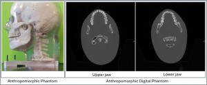
Digital Imaging Phantom: A digital anthropomorphic head phantom was utilized for computational analysis.
- Naso-occipital length: 23 cm
- Cranial breadth: 16 cm
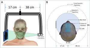
Device Geometry: The CBCT unit has the following geometry:
- Isocenter-to-source distance: 38 cm
- Isocenter-to-detector distance: 17 cm
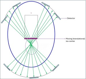
- A translational isocenter movement space was designed, taking into account kinematic constraintsconsidering the detector movement. This space is an 11 × 6 cm rectangular isocenter movable area starting 1 cm behind the bite point.
- With this geometry, currently only a limited-angle circular scan (approximately 270°) is achievable.
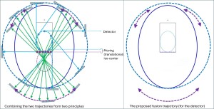
Source-Detector Trajectory Development: The proposed trajectory integrates two distinct scanning principles to acquire projections that enable the reconstruction of a larger imaging volume:
Principle 1: Modified Elliptical Isocenter Moving Scan
- This scan follows a modified elliptical pattern with tangential projection angles based on [2].
- Limitation: If the ellipse axis becomes too large, the reconstruction can result in a donut-shaped 3D region due to insufficient X-ray beams passing through the center of the field of view (FOV).
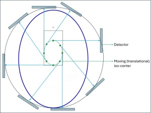
Principle 2: ROI-guided Optimized Scanning Based on Tuy’s Condition
According to Tuy's condition [3]:
- Every 3D voxel in the imaging volume must be intersected by an infinite number of X-rays from different directions.
- The X-rays should intersect the 3D voxels at a perpendicular angle to the tangent line drawn at the boundary of the volume of interest (VOI).
To meet these conditions as closely as possible, an ROI-guided algorithm was developed. This algorithm collects projections from a second elliptical iso-center placeable region positioned almost outside the original isocenter movement region.
Combining the scans to construct the fusion trajectory and reconstructing the images:
- Projection data from both scanning methods are combined to construct the proposed fusion trajectory, and an iterative reconstruction algorithm is applied to generate a 3D image.
- All trajectory and reconstruction simulations were performed using the TIGRE toolbox(MATLAB-GPU-based) [4].
- The Ordered-Subset Simultaneous Algebraic Reconstruction Technique (OS-SART) iterative reconstruction technique from TIGRE was employed in this study.