Imaging methods
When it comes to shoulder imaging, each method has its own set of advantages and limitations.
1. Radiography
It is a quick, inexpensive, and easily accessible approach for detecting fractures, arthritis, and shoulder dislocations. It has limits in terms of soft tissues, which are difficult to visualise [1].
The patient may stay upright, supine, or seated.
Patient position for each view are demonstrated and described in figure 1.

2. CT
Is another x-ray-based imaging approach. It is the gold standard for detecting fractures, including those that cannot be seen with traditional radiography.
The positioning of the patients is demonstrated and described in figure 2.
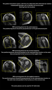
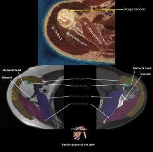
The scan should begin above the acromioclavicular joint and continue to the bottom of the scapula. The protocol should contain thin slices (at least 1.25mm) with a pitch of approximately 0.5 and the narrowest field of view possible (a FOV of 25 cm is preferred). After the image acquisition, we can use the data for the reconstructions; a sharp kernel paired with a bone window is needed for assessing the bony regions, and a normal kernel with soft tissues windows should be used for evaluating the soft tissues. Additionally, coronal and sagittal reformats can be obtained, as well as 3D reconstructions. The coronal reformat plan is parallel to the supraspinatus tendon while the sagittal is perpendicular to the supraspinatus tendon. The reconstruction planning is showed in figure 3 (being similar to the acquisition planes for the MRI exam) [1].
3. MRI
This is the gold standard for evaluating soft tissues, and it does not employ radiations, making it suitable for recurrent usage. The downsides of this approach include a prolonged acquisition time, which can cause claustrophobia in the patient, and limits in imaging the cortical bone.
The patient is positioned similar to the CT position (figure 2), but with the unaffected arm by their side. A coil is used to increase the signal to the region. After that axial, sagittal and coronal views are obtained. The planning of these sequences uses the supraspinatus muscles as a landmark, coronal views being parallel to it, while sagittal views being perpendicular to it, as shown in figure 3. Our protocol includes fat saturated protein density sequences (PD FS) in all planes, T1 sequences in sagittal plane, short tau inversion recovery (STIR) sequences is sagittal plane and a T2 sequence in coronal plane. Slices should be 3mm thick with a 10% gap between them, with a FOV between 20 and 25 cm. The coverage should be like the one described at the CT section (above the AC joint to the base of scapula) [1].
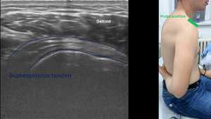
4. Ultrasound
Is a fast and dynamic method of evaluating the rotator cuff and the superficial structures of the shoulder. It uses ultrasound waves, which are harmless, allowing for repeated uses. Bony structures can not de examined in detail the same applying for the deep structures because of the ultrasound physics [2].
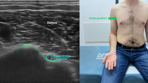
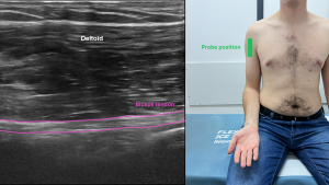
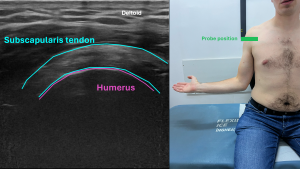
A musculoskeletal or superficial tissues preset is used on the ultrasound machine, coupled with a linear probe, with a high frequency. The patient is seated, with the affected arm at the side or resting on the torso. The scanning protocol is described in figures 4-8 also demonstrating the patient’s position and the structures that can be visualised [1,2].

5.Arthrography
Shoulder arthrography can also be done in order to evaluate labral tears, rotator cuff tears, capsular pathology and intra-articular loose bodies. Classically it was done using fluoroscopy or plain x ray, nowadays being done using CT and MRI. An injection with contrast substance (iodate for CT and gadolinium for MRI) is done under ultrasound guidance, fluoroscopic guidance or CT guidance in the joint space [1].
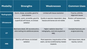
A brief comparison of the imaging modalities can be found in table 1.
Anatomy
Understanding the anatomical relationships between them is the first step towards understanding the imaging of this region.
Glenoid labrum is a fibrocartilaginous structure that runs along the margin of the glenoid cavity. It has a triangle cross section, with the base attached to the cavity's edges and the free edge narrow and sharp [3,4].
The labrum is best evaluated on MRI, tears in it’s structure being bright on T2 due to the fluid.
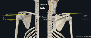
Bones
The bones that are encompassed in the shoulder are represented by the clavicle, scapula (shoulder blade), and the proximal part of the humerus. Their parts are being illustrated in
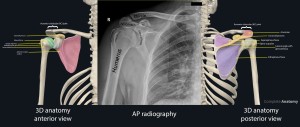
On Xray, bones are radiopaque, cortical bone being more radiopaque while medullar bone being less radiopaque (being less dense). A similar aspect is also seen on CT scan, but we can make 3D reconstructions of the bones, especially useful for preoperative planning.
MRI is not ideal for bone imaging, but we can evaluate the bone marrow (bright both on T1 and T2) and bone marrow oedema (bright on T2, PD, STIR and dark on T1).
Ultrasounds do not penetrate bones, being limited to visualising only the periosteum and cortical bone.
Muscles
Rotator Cuff Muscles
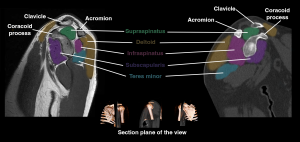
This set of four muscles and their tendons stabilises the shoulder by retaining the humeral head in the glenoid cavity. There are four muscles: supraspinatus, infraspinatus, teres minor and subscapularis. They are presented and described in figure 10.
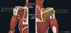
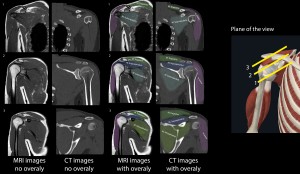
The muscles are also highlighted in axial, coronal, sagittal planes as viewed on MRI and CT. An sketch was also included.
Radiography does not directly view the rotator cuff muscles, but we can suspect a rotator cuff tear if the humeral head is migrated superiorly. Also, calcifications at the level of rotator cuff tendons can be seen on radiography.
CT is also not very sensitive in evaluating the rotator cuff muscles, but we can see fatty infiltration, muscle atrophy and calcifications.
MRI is the best imaging method for evaluating the muscles and tendons of the rotator cuff, including tears (bright on T2), tendinosis (intermediate T1 and T2 signal) and atrophy. Also, MRI can detect muscle oedema.
Ultrasound is also great at evaluating the rotator cuff muscles, while also allowing for a dynamic assessment. Partial tears appear as focal hypoechoic areas while full thickness tears are seen as discontinuity of the tendon.
Ligaments
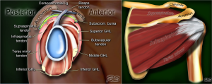
The structures that connect the bony parts, providing stability of the shoulder are: glenohumeral ligament (that has a superior, middle and inferior part), coracohumeral ligament, transverse humeral ligament and coraco-acoromial ligament [4]. They are represented in figure 11.
They can be seen on x ray and CT if they are calcified. MRI can detect tears, fraying or thickening of these structures. Ultrasound can be helpful in evaluating the stability of joint and ligaments.
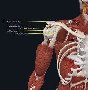
Bursae
Synovial bursae which are fluid-filled sacs are found around the joint capsule, help with shoulder mobility. The shoulder bursae are as follows:
- The subacromial and subdeltoid bursa are located between the joint capsule and the deltoid muscle.
- The subacromial bursa sits between the joint capsule and the acromion.
- The subcoracoid bursa sits between the joint capsule and the coracoid process.
- Coracobrachial bursa is found between the subscapularis muscle and the tendon of the coracobrachialis muscle.
- The subscapular bursa (subtendinous) is located between the joint capsule and the tendon of the subscapularis muscle [4].
They are also illustrated in figure 12.
Radiography can show calcified bursae in chronic bursitis. CT in addition to the classic radiography can also demonstrate fluid collections. MRI is best for evaluating bursitis, the bursae being bright on T2 images. Ultrasound can show fluid effusions, and while doing an dynamic exam, we can detect impingement.