Introduction
With recent advancements in CT imaging, especially with AI-driven image reconstruction methods primarily trained on patient data, there is a gap between the technical image quality metrics combined with simple phantoms and clinical image quality requirements [1]. Bridging this gap requires development of more realistic anthropomorphic phantoms that mimic diverse patient morphometries and potential disease variations. 3D-printing offers a promising solution, allowing for the designing of customised, affordable, and flexible models, to represent patient anatomy [2].
Anthropomorphic lung vessel model
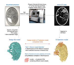
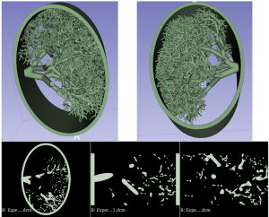
An in-house algorithm was used to generate a model of a lung vessel distribution based on patient data obtained from lung vessel trees of cadavers [3]. The algorithm included a mathematical description of lung vessels growth from the centre of the thorax (heart) towards the pleura, with progressively decreasing length and diameter. The lung vessel model, with diameters ranging from 1 to 8 mm, was designed to mimic a slab on the patient lung in the cranio-caudal direction and was encased in an elliptical rim for protection and easy transport. The lung vessel models are generated in a pseudo-dicom format which can be segmented (3D slicer) and converted into STL files for input into 3D printers (Fig. 1).
3D printing of the lung phantom
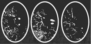
Based on previous research evaluating different 3D printing techniques and materials, HP MultiJet Fusion (MJF) technology and thermoplastic polyurethane (TPU) powder were selected to print the model. With HP MFJ, fusing and detailing agents are selectively deposited onto the thermoplastic powder raw material, with a voxel by voxel accuracy, according to the manufacturer, melting and fusing the powder material layer by layer [4]. This technique allows printing without support scaffolding, as the raw powder material holds the printed structures in place, though exit spaces must be incorporated to remove powder after printing. The wide range of attenuation between the powder 3D printing material and its solid fused form (with at attenuation of ~ 60 HU at 120kV under CT imaging, similar to blood in fused form and ~ -630HU at 120kV in CT imaging in raw powder form, Fig. 2), was exploited to create a pseudo-multimaterial printed object with this technique. The design included selected vessel regions specifically structured to trap some powder after printing, for simulating tissue attenuation variability in the human lung parenchyma.
Micro-CT scanning and printing accuracy evaluation
The 3D-printed lung phantom was scanned in micro-CT system with voxel size 0.0798x0.0798x0.0798 mm3 (Phoenix V|tome|x M micro-focus CT at the Irish Soil and Root Imaging Facility (IRSI) in UCD) [5]. CT images were segmented in 3D Slicer through thresholding to extract the vessels, and the CT-phantom model was generated (CT_model).
The thickness of the structures and vessels in the CT-phantom model was measured using Measure Thickness tool in MeshInspector to test if the model was printed within the 3D printer resolution stated by the provider (0.25mm for minimum details, 1-2 mm for minimum wall thickness; with stated accuracy of 0.9% in the XY plane and up to 1.8% in the Z direction, with minimum error limits of 1 mm in XY and up to 1.5 mm in Z) [6].
Geometric accuracy of the printed vessels was assessed globally to evaluate overall accuracy and locally within selected volumes of interest (VOIs) containing vessels of different sizes (Fig. 3). The vessel diameters within VOIs were measured at ~30 equivalent locations (Test_1). Differences between the CT-phantom model and design file (sent to the 3D printer) were analysed globally by registering the whole volumes, and locally by registering local VOIs. Statistical distance analysis was performed using Distance Compare function in MeshInspector which generates coloured distance maps and average absolute distance (AAD) values between the model mesh and the lung vessel tree segmented from micro-CT images of the 3D-printed phantom (Test_2).