Congress:
ECR25
Poster Number:
C-15787
Type:
Poster: EPOS Radiologist (educational)
DOI:
10.26044/ecr2025/C-15787
Authorblock:
T. Mayor Simonatto, P. Akissue De Camargo Teixeira, C. Rossi Saccarelli, L. Yamashita, V. C. Camargo De Siqueira Ferreira, V. L. N. Omura, L. Moyses, D. Gregolin Giannotti; São Paulo/BR
Disclosures:
Thais Mayor Simonatto:
Nothing to disclose
Patricia Akissue De Camargo Teixeira:
Nothing to disclose
Carolina Rossi Saccarelli:
Nothing to disclose
Ligia Yamashita:
Nothing to disclose
Vera Christina Camargo De Siqueira Ferreira:
Nothing to disclose
Vivian Larissa Nakamura Omura:
Nothing to disclose
Larissa Moyses:
Nothing to disclose
Daniela Gregolin Giannotti:
Nothing to disclose
Keywords:
Breast, Mammography, MR, Ultrasound, Diagnostic procedure, Normal variants, Screening, Foreign bodies, Image verification, Prostheses
We were able to exhibit distinct implant-related images on mammograms, either subtle or evident, and correlate these findings with alterations identified through other methods, such as ultrasound and MRI. The major findings on the analyzed mammograms are as follows:
- Saline implants and expanders
- Saline implant expanders’ valves are usually very conspicuous on mammograms. These present in various shapes and are mostly anterolaterally localized.
- In a rupture context, the implant can be found deflated.
- Due to its standard hypodensity, other related findings are usually remarkable on these types of implants.
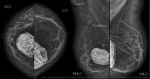
Fig 1: CC and MLO views, without Eklund maneuver - bilateral saline implants, ruptured: both saline implants are deflated. (reference: Shah AT, Jankharia BB. Imaging of common breast implants and implant-related complications: A pictorial essay. The Indian Journal of Radiology & Imaging. )
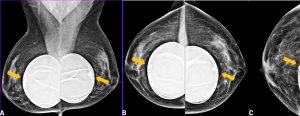
Fig 2: (A) MLO views, without Eklund; (B) CC views, without Eklund; (C) CC view, Eklund.
Bilateral saline expanders. The implant's valves are easily recognized, symmetrical, and in most cases are anteriorly / anterolateraly located.
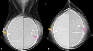
Fig 3: (A) MLO views, without Eklund; B) CC views, without Eklund.
Bilateral saline expanders. In this case, the valves are asymmetrically located, which may indicate rotation.
- Previous and current ruptures
- Irregular surface with a breakage point and silicone leakage are possible to be observed, in selected cases.
- Extracapsular ruptures determinate more noticeable signs than purely intracapsular ones: the silicone is opaque on image and the fibrous capsule along with its calcifications often blur any intracapsular rupture evidence.
- Previous extracapsular ruptures can determine undefined peri-implant opacities adjacent to the current implant’s fibrous capsule, or amorf opacities on mammograms with no current implants and compatible history. These would represent the residual silicone from previous leakage.
- Free silicone can simulate capsule thickening.
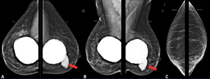
Fig 4: Case 1, rupture - (A) CC views, without Eklund; (B) MLO views, without Eklund; (C) MLO views, Eklund maneuver.
Both implants were 30 years of age, hardened. Notice the significant amount of calcifications surrounding the implants. On the left breast, a conspicuous extracapsular rupture point is noticed, leaking free silicone to the, and no evidence of this finding is seen on Eklund maneuver images. No hyperdense ipsilateral lymph node is evident in this exam.
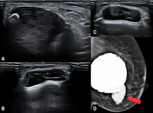
Fig 5: Case 1, rupture - (A), (B) , (C): Ultrasound (US) images; (D) Mamogram (MG), MLO views without Eklund.
The red arrow demonstrates the extracapsular rupture point. US identifies a peri-implant heterogeneous fluid collection, representing free silicone permeating the parenchyma. US x MG correlation demonstrates morphology correspondence of the silicone collection.
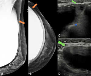
Fig 6: Case 2, rupture - (A), (B): MG - MLO and CC views, without Eklund, left breast; (C), (D): US, left breast.
Retropectoral implant, exhibiting peri-implant amorphous density (upper-outer, orange arrows), extending to the axilla. This reduces the definition of the implant's contour and suggests extracapsular rupture. The US images confirm this hypothesis, as it shows rupture points of the fibrous capsule and snowstorm-like features and a heterogeneous collection surrounding the implant (green arrows). Since the implant is retropectoral, the free silicone is contained by this muscle and doesn't extend to the parenchyma. This case also showed atypical lymph node with silicone deposit.
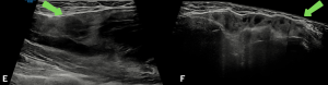
Fig 7: Case 2, rupture - (E), (F): US, left breast.
Retropectoral implant, exhibiting peri-implant amorphous density (upper-outer, orange arrows), extending to the axilla. This reduces the definition of the implant's contour and suggests extracapsular rupture. The US images confirm this hypothesis, as it shows rupture points of the fibrous capsule and snowstorm-like features and a heterogeneous collection surrounding the implant (green arrows). Since the implant is retropectoral, the free silicone is contained by this muscle and doesn't extend to the parenchyma. This case also showed atypical lymph node with silicone deposit.
Fig 8: Case 3, rupture, bilateral - (A): MLO view, without Eklund.
Retropectoral implants, both exhibiting peri-implant amorphous densities on the upper quadrants (pink arrows). These also indicate extracapsular ruptures contained by the pectoral muscle.
(B), (C): US of the left axilla, demonstration of silicone deposit on various lymph nodes (snowstorm signal).
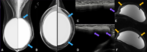
Fig 9: (A), (B): MLO and CC views, without Eklund; (C), (D): US images; (E), (F): MRI, left breast, T2 water-saturation.
Retropectoral implants, with amorphous density surrounding the left implant (blue arrows). This patient had history of a previous extracapsular rupture on this side - the previous implant was substituted.
The US images demonstrate free silicone inside the capsule, which interferes on the assessment of the elastomer (purple arrows). A MRI was performed, which confirmed the integrity of the implant, and showed free silicone between the elastomer and the fibrous capsule (yellow arrows) - residual silicone from the previous rupture.
- Implant folds
- Although not a pathology, implant folds may appear on imaging methods and must not be confounded with ruptures.
- These folds may manifest themselves on mammograms as ondulations, sinuous irregularities or even thin hyperdense lines within the implant itself.
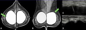
Fig 10: (A): CC view, without Eklund; (B): MLO view, without Eklund; (C), (D): US images.
Deep sulks / folds and ondulations are observed on both implants (green arrows), corresponding the the accommodation radial folds we may observe on ultrasound or MRI images. These don't necessarily translate to significant implant alteration, but can be mistaken for implant fractures/ruptures. If the folds are too deep or too prominent, a more detailed assessment may be indicated.
- Fibrous capsule calcifications
- May present as peri-implant high-density irregularities.
- On a zoomed view, these irregularities can be better characterized as high density round or heterogeneous calcifications.
- The calcifications can be dislodged on Eklund maneuvers along with the fibrous capsule, simulating parenchymal localization. In this case, assessment of all the views (CC and MLO, with and without Eklund) as well as their distribution following the implant’s surface may differentiate between capsule and parenchymal calcifications.
- These calcifications may occur on fairy newly allocated implants, increasing with time and might form a hard and opaque irregular shell-like structure. These may be clinically assessed as implant hardening.
- Calcifications can project themselves on US imaging as linear or thick structures forming a marked posterior shadow. They can be singular or coarse, and of diffuse or sparse distribution.
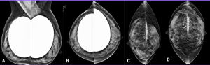
Fig 11: (A): MLO view, without Eklund; (B): CC view, without Eklund; (C):MLO view, Eklund; (D): CC view, Eklund.
Peri-implant calcifications are observed - these would form over time, on the fibrous capsule. These tend to be coarse and heterogeneous, and determinate a certain irregularity of the capsule itself, on both mammogram and ultrasound images. Notice that after the Eklund maneuver, the calcifications overlap the breast parenchyma - on these cases, special care is in order, aiming to avoid confusion between capsule and parenchymal calcifications.
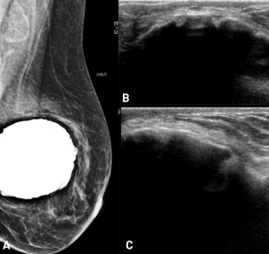
Fig 12: (A): MLO view, without Eklund; (B), (C): US images.
28 year old implant. The great amount of coarse calcifications cause the capsule to be irregular, and on this case are conspicuous on ultrasound images. Hardening of the implant can be clinically be present. Since the implant evaluation is frustrated on ultrasound images by the posterior shadow artifacts, a MRI should be the method of choice in order the assess the implant's integrity.
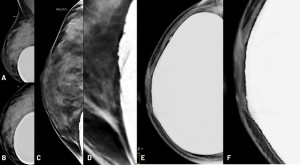
Fig 13: Cases 1 (A-D, 44 years old patient, 19 years old implants. ) and 2 (E-F, 51 years old patient, 27 years old implant) - right breasts.
(A): MLO view, without Eklund (B): CC view , without Eklund (C): MLO view (Eklund) (D): zoomed MLO view (E): CC view, without Eklund (F): zoomed CC view
In both cases (standard CC and MLO views), peri-implant irregularities are observed, with higher density areas on its surface. On the Eklund maneuver radiography (D), a zoomed and partial implant image of the right breast was obtained, which better characterizes these higher density areas as fibrous capsule’s calcifications. Regarding case 2, the calcifications are evident on standard CC view.
- Implant rotation
- The signs of implant rotation can be better discriminated if the implant contains an identification microchip, which is opaque on imaging, of a unique shape, and on a normal scenario faces the thoracic wall. Furthermore, the chip does not appear on a standard mammogram.
- The anteriorly, laterally or medially dislocated microchip can be identified on different mammogram views, without the Eklund maneuver. However these can be difficult to spot due to the silicone density on silicone implants, and may require intensity windowing resource to be assessed.

Fig 14: (A): case 1 - MLO view, without Eklund; (B): case 2 - MLO view, without Eklund, treated image.
On both cases we can notice the implants' identification chips (red arrows), which are usually facing the thoracic wall and thus unseen on a conventional mammogram. The lateralized chips' may imply some degree of implant rotation, which was confirmed on both cases through MRI.
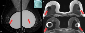
Fig 15: (A): MLO view (treated image); (B)/(C): MRI - T1 and T1 fat sat; (D): silicone gel implant with an electronic identification enablement chip. 46 years old patient, 4 years old implants. On the standard mammogram, the identification device can be seen on both implants (red arrows). These devices usually face the thoracic wall, and are rarely seen on normal circumstances. This feature can indicate implant rotation, as confirmed though the following MRI, on which both implants are medially rotated, with lateralization of the vedation seal and identification chips.
- Peri-implant densities
- Peri-implant hyperdensities can translate indirect signs of fluid collections (seromas), capsule thickening with or without associated inflammation or even extracapsular ruptures with contained silicone (in a retropectoral implant context, for example). They may also represent solid formations, such as subcapsular masses.
- These can also be associated to coarse peri-implant calcifications.
- Asymmetric densities in a routine mammogram may indicate the need of a thorough implant-directed evaluation.
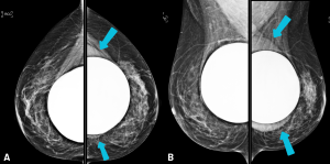
Fig 16: (A): CC view, without Eklund; (B): MLO view, without Eklund - retropectoral bilateral implants.
Peri-implant homogeneous density, with a regular contour, is observed on the left breast (blue arrows). Notice that even though it is denser than the surrounding tissue, it's still less dense than the silicone implant. This patient was submitted to additional imaging through US and MRI, which yielded peri-implant homogeneous seroma. The report of this finding was important to establish the need for a more thorough evaluation of the left breast.
- Capsule thickening
- The fibrous capsule can be identified as a linear, homogeneous and regular hyperdense line that follows the structure and curvature of the implant.
- Thickened fibrous capsule can present both as a regular or an irregular structure, and may be associated to calcifications.
- Thickened capsule may be a very sheer imaging finding and contralateral evaluation can ease this assessment.
- If no coarse calcifications explain this finding, the hypothesis of an inflammatory process (capsulitis) may be considered, specially if hardening is present, and further investigation would be in order.
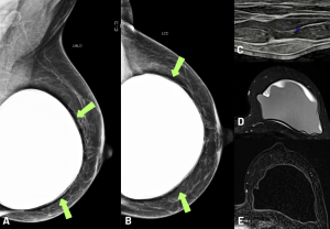
Fig 17: (A), (B): MLO and CC views, without Eklund; (C): US; (D): MRI, T2 FAT-SAT; (E): MRI, T1 contrast-enhanced, subtraction.
A thickened line surrounding the implant was reported, which represented a thickened fibrous capsule (green arrows), and additional evaluation was suggested.
US and MRI confirmed capsule thickening, with focal, nodular images on ultrasound. MRI identified inflammatory signs (capsulitis), and peri-implant liquid collection associated to an amorphous, low signal content.
The possibility of BIA-ALCL (breast implant associated lymphoma) could not be dismissed, and a detailed histopathological analysis through biopsy was indicated.